"KICK the key" - Remote SmartSDR and a wired PTT Footswitch
In my previous blog entry, I was touting the awesomeness that is the FlexRadio 6400 operated remotely via SmartSDR, and how to interface it with WSJT-X. It's working well enough that, after about 3 hours of chasing them on Easter Sunday, I was able to add 4U1UN to the FT8 logbooks!
All this fuss about the Flex 6400 and SmartSDR is all part of the run-up to Florida QSO Party (FQP). N4TP will be fielding a remote radio at the Tampa Amateur Radio Club, so I'm getting myself acquainted with remote ops.
Having run a few contests previously, I (like most hams) have my preferred "contest setup". I personally enjoy using my Yamaha CM500 headset (same quality as a Heil headset and waaaaaaay cheaper!) with a PTT footswitch, so that I have my hands available for logging. With this setup in mind, I wondered how easy it would be to have a local PTT footswitch trigger the PTT on the radio remotely. Thankfully, FlexRadio has already thought of this and made it super simple to do via SmartSDR CAT. The main steps are:
1) build the PTT hardware interface between your PTT footswitch and the PC
2) Open SmartSDR CAT and create the PTT software interface
Since I use a simple 1/4" footswitch from Amazon, I wanted to interface that with my laptop. The main method for doing this is over RS-232 Serial, which of-course most modern laptops no longer have. So, I had to opt for a USB-to-serial dongle to get it set-up. The parts list is below:
Parts List:


Now, test it out: when you press the PTT footswitch, it should trigger MOX on the SmartSDR!
All this fuss about the Flex 6400 and SmartSDR is all part of the run-up to Florida QSO Party (FQP). N4TP will be fielding a remote radio at the Tampa Amateur Radio Club, so I'm getting myself acquainted with remote ops.
Having run a few contests previously, I (like most hams) have my preferred "contest setup". I personally enjoy using my Yamaha CM500 headset (same quality as a Heil headset and waaaaaaay cheaper!) with a PTT footswitch, so that I have my hands available for logging. With this setup in mind, I wondered how easy it would be to have a local PTT footswitch trigger the PTT on the radio remotely. Thankfully, FlexRadio has already thought of this and made it super simple to do via SmartSDR CAT. The main steps are:
1) build the PTT hardware interface between your PTT footswitch and the PC
2) Open SmartSDR CAT and create the PTT software interface
Since I use a simple 1/4" footswitch from Amazon, I wanted to interface that with my laptop. The main method for doing this is over RS-232 Serial, which of-course most modern laptops no longer have. So, I had to opt for a USB-to-serial dongle to get it set-up. The parts list is below:
Parts List:
- USB-to-serial-female dongle cable - $8.99 from Amazon
- DB9 male "breakout" connector - $8.99 from Amazon
- 1/4" female locking jack - $5.99 from Amazon
- 1 to 2 ft. of spare dual-lead 12 gauge speaker wire - surplus from another project
Tools needed:
- soldering iron*
- * now-a-days Amazon carries a soldering iron kit with a multi-meter and a pocket screwdriver set, all for $26. That's super cheap. No endorsement, just sayin'.
- 60/40 Tin/Lead (Sb/Pb) rosin-core solder
- wire strippers (like my Irwin VISE-GRIP Wire Strippers: the greatest strippers* on the planet!)
- * greatest WIRE strippers on the planet - not sure how they compare to other strippers
- multi-meter with continuity checker
- a third-hand work platform
- small eyeglass screwdrivers: 1x flat-head, 1x philips head
Our objective is that we need to connect pins 7 and 8 (aka RTS) to each other on the DB9 connector. When the PC detects this connection, the SmartSDR CAT software will trigger the radio's PTT button. Easy peasy, right guys? Right?
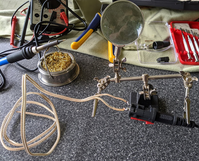
So, lets start with a build-in-progress photo:

Above, you can see the tools and the wire/jack. We're already starting to create mayhem, so lets get to it!
PROTIP #1: I plugged the footswitch into the jack, so I could use the footswitch wire with the third hand's clip. YMMV, see store for details. And this will definitely void your warranty, because there wasn't one to begin with. OK LETS HAVE SOME FUN!
PROTIP #2: If you use the same locking 1/4" jack that I did: make sure that when it's pulled apart for soldering, that the red locking slider doesn't come undone and shoot the spring below it across the back porch so that you then spend the next 30 minutes looking for a small 1" long black spring on a gigantic back porch. Yknow, not speaking from experience or anything.

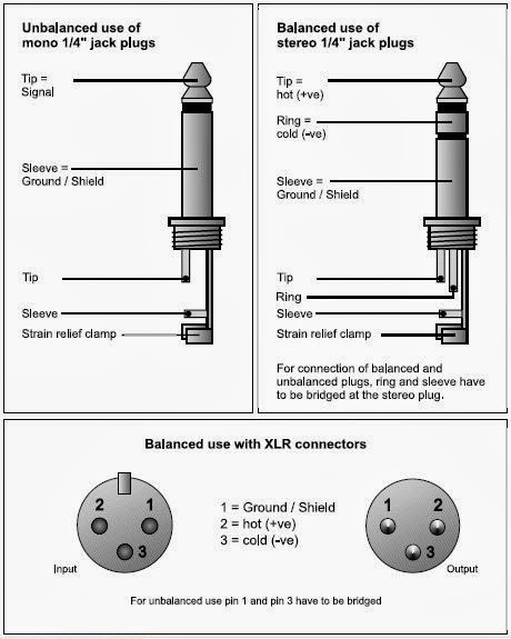
I stripped about 1/4" of shielding off the ends of the wires, twisted the strands together, then connected one wire to lead #1 (the "tip" of the 1/4" plug/jack), and one wire to lead #2 (the "ring" of the 1/4" plug/jack), and lead #3 is unused. This is because the footswitch is just "tip" and "combined ring&sleeve", aka mono aka unbalanced. A nice diagram from the Interwebs of what "balanced vs. unbalanced" 1/4" jacks look like is below (ignore the "Balanced use with XLR connectors" section at the bottom):
Since all we need to do is to connect tip to sleeve, I checked with the continuity check function on the multi-meter and made sure when the footswitch was triggered, the two wires connected.

Since we're using RTS shorting to trigger the PTT, we will connect the speaker wires to pins 7 and 8 on the DB9 breakout board. I stripped away about 1/8" of wire from the other side of the leads, twisted the strands tightly together, and screwed them into ports 7 and 8. It doesn't really matter which lead goes where, only that they're absolutely not touching each other at all when the footswitch is not activated. I then used the multi-meter leads in pin 7 and 8 on the DB9 plug to check that I had good connections.

The finished result: a 1/4" female jack-to-DB9

Then, I just plugged that into the USB-to-serial cable, and plugged that into my laptop!
Once you plug your new cable in, next comes the software part. First, we need to identify which COM port the cable is using. To do so in Windows 10, you can:
- right-click the START button and click "Device Manager"
- expand the "Ports (COM & LPT)" option
- identify your USB-to-serial dongle, and note the COM port it's connected to
- For this example, we'll say it's on COM13
Now: open SmartSDR and SmartSDR CAT, and connect both to the radio. Then, inside of SmartSDR CAT, configure the PTT button:

a. Name: PTT-Footswitch
b. Port Protocol: PTT
c. Port Type: Serial
d. Serial Port: Existing
e. Client COM: COM13 (whatever COM port your USB-to-serial dongle is)
f. VFO A Slice: A
g. RTS: RTS Enabled
h. Polarity: Active Low
i. Auto Switch TX Slice: Enabled
Now, test it out: when you press the PTT footswitch, it should trigger MOX on the SmartSDR!

Comments
Post a Comment