Dual-Band Copper Pipe J-Pole: it's MAGIC!
A few weeks ago (before getting my FTM-100DR), I was rocking a Baofeng UV-82HP. Great little radio, and puts out 8 watts: impressive for a handheld! I replaced the included rubber-duck antenna with a Hypario 771, which really helped matters out when hand-held. When mobile, I installed a Tram 1185 mag-mount antenna (which also works well, especially with the new FTM-100DR!).
I wanted something a little more substantial, though, for when operating at my primary/secondary QTHs. So, I decided that a pair of dual-band copper pipe j-pole antennas were in my future.
Now I don't take credit for the design (that's from N6JSX): just wanted to share my experience building them, and a few tips on what to/not to do!
First, the quasi-finished product (this is before silicone and heat shrink, and using CPVC pipe caps until fully tuned!):

Not too shabby, IMO. Now: onto the instructions!
I followed the instructions listed at eham.net by N6JSX, but specifically used the dimensions below:

I also used the alternate feed method, listed below:

Ok: before I list materials and tools - I'm providing links for description only. I don't endorse any specific product (except the Amphenol SO-239***, but more on that later!), so get what you feel comfortable with!
So now, here's a materials list (per antenna):
- 1x 1/2" type L copper tubing ($15.40): 10' piece, cut-down to the following lengths:
- 1x 63" in length
- 1x 19" in length
- 1x 1.75" in length
- 2x 1/2" copper tee ($1.86)
- 2x 1/2" copper pipe cap ($1.20)
- 1x Amphenol SO-239 connector ($3.89)
- 1x 7" 12 AWG stranded wire (~$1)
- 1x 5/8" Heat Shrink ($3.96)
Total with tax was about $27, unless you got some of this hanging around (which I did: winning!).
Now, the tools/supplies list is:
Now, the tools/supplies list is:
- Propane Torch
- Soldering Iron
- Copper Tubing cutter
- Plumber's Soldering Flux, solder, and sand paper or silicone carbide sanding screen (recommended!)
- Here's a nice kit with everything needed from Home Depot
- 60-40 rosin-core solder
- 1/2" fitting brush
- Drill with a bit big enough for your wire to go through without too much rubbing (3/16 should work fine if using 12 AWG)
- Silicone caulking (for sealing the wire going through the hole in the 70cm element)
Tips/Tricks on assembly:
The bits of advice I can give to you on these are:
- GET AN AMPHENOL SO-239 CONNECTOR!!! I'll say it again: GET AN AMPHENOL SO-239 CONNECTOR!!! The cheap "5 for $7" SO-239's on Amazon are fully plated, and solder doesn't stick to them at all. Seriously, one more time: GET AN AMPHENOL SO-239 CONNECTOR!!!
- Drill the hole in the 70cm element. Then, run the 12 AWG through it and through the bottom of the 70cm element, THEN solder it to the center-post of the SO-239 connector: it's muuuuch easier that way.
- After ample cleaning, heat the tee-fitting on the 70cm element with your torch, then barely heat the surface-plate of the SO-239 while applying solder. What you're trying to avoid is overheating the SO-239 connector, and melting the center insulator. This is best accomplished with 2 people.
- Get an SWR meter*** for testing and tuning. Before soldering the wire to the 2m element, attach it temporarily with a hose clamp. Once you find the spot for it, rough that spot-up with sand paper, hit it with the torch, and apply the solder. Also easier with 2 people.
- It's a good idea to tin your wires before working with them.
- Follow this video right hurr on how to properly solder copper pipes together. Also: once you solder your joints, make sure you wipe-away all excess solder flux. Otherwise, your antenna will start to turn green and corrode. This is not good.
*** DO NOT GET THIS ONE: IT DOESN'T WORK!!!
And that's about it! I'm waiting on my new SWR meter to show up, so once I get it, I'll put my results in. According to the eham article, though, using 3/4" type L gave the following VSWR readings:


Not too shabby for about $27 in parts and an hour's worth of time. I was impressed with the increased transmit distance, but was floored with the increase in receive ability! YMMV, but I think you'll like building this: I know I did!
Update #1 11-3-2017:
So yesterday, I finally got my new SWR meter: a SURECOM SW-33 from Amazon. Looks like this antenna is doing a whole lot better than I thought! On 146.52 MHz, it's doing a 1.12:1 SWR (even using my current, very crappy RG-58 feedline) and does even better on 446.000 MHz - a very impressive 1.04:1 SWR:


Even on my Baofeng UV-82HP, it's doing awesome - 1.06:1 SWR on 146.520 MHz and an epic 1.01:1 SWR on 446.000 MHz :


Update #2 11-3-2017:
So, I was asked how I have this antenna mounted. I currently have it zip-tied to a speaker tripod from a PA system. Yes, you're right: it's terrible. But, it works!

/u/me_too__ posed an idea in my /r/amateurradio post about using a mic stand instead of a speaker stand. Well, I think you definitely can, using a short piece of leftover pipe, soldered to a copper end cap, soldered to a 3/8" male to 5/8" female mic stand adapter, connected to your mic stand. Here's a crude not-to-scale drawing:

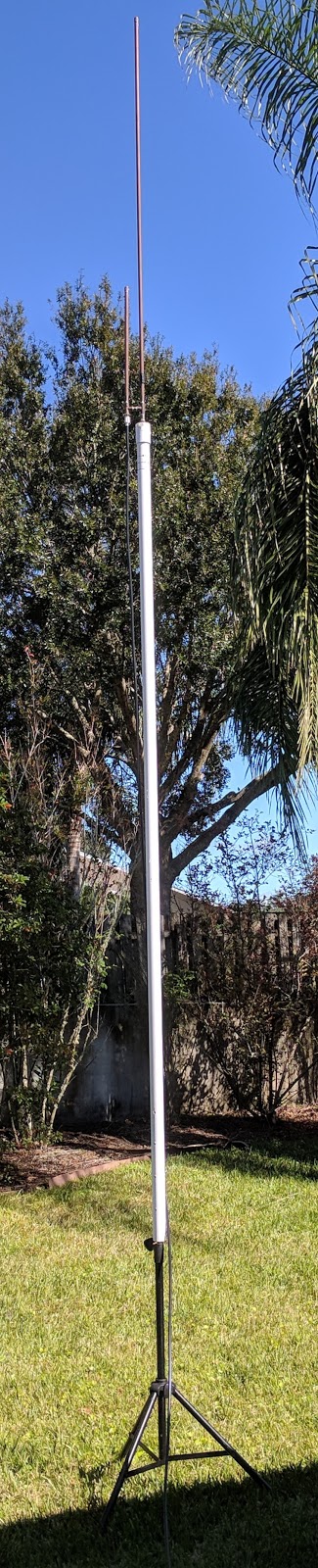
So, I'm assuming this will be the final countdo...errrr...update. Over the weekend, I decided to make a mast-extension to my setup, using:
The end result (minus the guy wires):

Yeah, buddy! To paraphrase local musician Greg Billings: GET ON UP (antenna)!
Also: this gives me a great platform to eventually build an inverted v dipole antenna for HF work. Gotta get an HF rig first, though!!
Then, the next thing I worked on was the feedline. I was using cheapo Radio Shack RG-58 which, while good for HF, is very lossy on 2m/70cm. But, thanks to a fellow local ham N9EE, I acquired a 60'-ish length of RG-213, which is great cable for 2m/70cm. He also hooked me up with a few solder-type PL-259 connectors. As far as the technique used to solder the ends on: I followed the steps listed in this video exactly, and it worked well! The end result (on the left with a PL-259 to BNC adapter, with the RG-58 on the right):

Now, a few hints that I learned:
So, I was asked how I have this antenna mounted. I currently have it zip-tied to a speaker tripod from a PA system. Yes, you're right: it's terrible. But, it works!

Update #3 11-3-2017:

You'll have to either cut the 3/8" threads off of the mic thread adapter, or (easier imo) drill a 3/8" hole into the end cap so that the cap and adapter are flush when you go to solder them together, but this shouldn't be too difficult. Then, you can just thread the j-pole into your mic stand!
Update #4 11-6-2017:
- 1x 1-1/2" rigid-wall pvc pipe (~15' long)
- 1x 1-1/2" to 1/2" threaded pvc adapter
- 1x 1/2" copper thread adapter
- 1x 1/2" type L copper pipe (~3" long)
- 3x 10/24 (2" long) threaded bolts (for connecting PVC to speaker stand)
- 3x 10/24 wing-nuts (for connecting PVC to speaker stand)
And tonight, I'll be setting it up for guy-wires, using the following:
- 6x 10/24 eye bolts
- 6x 10/24 hex nuts, washers, and lock washers
- 550lb paracord
- 3x Army surplus 12" tent stakes
Remember, this is all built as a quick set-up and tear-down: put it up when wanting to use it, and take it down afterwards. So I think paracord is ok for this scenario.
The end result (minus the guy wires):
Yeah, buddy! To paraphrase local musician Greg Billings: GET ON UP (antenna)!
Also: this gives me a great platform to eventually build an inverted v dipole antenna for HF work. Gotta get an HF rig first, though!!

Now, a few hints that I learned:
- Working with wire this thick (0.405" exterior dimensions vs. 0.19" exterior dimensions for RG-58) can be tricky, as it doesn't like to bend easily. Remember: this is a good thing, as the internal insulator is thick! Be warned: you may need another set of hands to hold the wire at the angle you need when flowing solder on the braid, or through the holes of the connector to the braid.
- Trim the jacket back first, then tin the braid as shown in the video. Don't worry about tinning too much: it's easier than not tinning enough and having it come apart on you.
- Twisting on the connector to the jacket is not as easy as it looks: have a pair of pliers or channel locks at the ready!
- From N9EE and the video: Once you twist-on the connector, BUT BEFORE YOU SOLDER THE CONNECTOR, check with a multi-meter to ensure that there isn't a short between the jacket/braid and the center conductor/pin.
- My advice: check before soldering, after soldering, and once both ends are on: check end-to-end continuity between "braid-to-braid", and "center pin-to-center pin".
Since getting the antenna up in the air with the new feedline, my signal has increased drastically. I can now hit a System Fusion/Wires-X repeater that's about 25 miles away without difficulty.
Just when I thought I was out...
Ok: just a few more pictures, to maybe help clarify things:

This pic shows the end-result. This shows the solder-point on 2m element covered in heat-shrink tubing, the silicon-sealed hole on the 70cm element, and the bottom of the 2m-side tee-fitting soldered into a threaded adapter for the PVC cap. Using this set-up (with copper or PVC caps on the tops of the elements) should make this antenna completely water-tight.

The second pic is a close-up of the soldering between the 70cm tee fitting and the SO-239 connector. You'll have to have a buddy help with this (ideally), but what you'll want to do is:
Update #5 12-13-2017:
Ok: just a few more pictures, to maybe help clarify things:

This pic shows the end-result. This shows the solder-point on 2m element covered in heat-shrink tubing, the silicon-sealed hole on the 70cm element, and the bottom of the 2m-side tee-fitting soldered into a threaded adapter for the PVC cap. Using this set-up (with copper or PVC caps on the tops of the elements) should make this antenna completely water-tight.

The second pic is a close-up of the soldering between the 70cm tee fitting and the SO-239 connector. You'll have to have a buddy help with this (ideally), but what you'll want to do is:
- hold the SO-239 with pliers, away from the fitting (as the wire should already be soldered to the center-post of the SO-239)
- heat the fitting first, making sure to heat from the bottom
- once the fitting is sufficiently hot to melt solder, push the SO-239 to the fitting and quickly heat-and-solder.
- make sure you do so quickly, as prevent the center insulator of the SO-239 from getting too hot and melting
Joseph,
ReplyDeleteGreat build, I found your steps to be pretty straight forward. One thing I ended up changing was I cut slits in the tee where the connector goes, and used a hose clamp to make the physical/electrical connector-I went through two melted connectors before I opted for a clamp connection rather than a soldered one. I've posted some pictures online, you can find a link to them here: https://www.instagram.com/p/BhZj6TEA_ia/?hl=en
Thanks!
Barrett, W0ASB
Barrett,
DeleteThat's awesome: I'm glad that it could inspire you! If you can email me a few of those close-up pictures in high-res, I'll be glad to post them on here for others to benefit from!
Two connectors melted. Solder refuses to stick till it's hot, and heat melts the insulation :(
ReplyDeleteWill try some mechanical connection tomorrow.
When looking for a trusted Tin Coated Copper Wire Manufacturer India, quality and performance are the most important factors. Tin coated copper wires offer excellent conductivity, corrosion resistance, and durability, making them ideal for electrical, automotive, and industrial applications. Choosing an experienced manufacturer ensures high-quality products that meet industry standards and deliver long-lasting performance. A great solution for businesses seeking reliable wiring components.
ReplyDeleteFor more visit below links
Braided tin coated copper wire Manufacturer India
Stranded tin coated copper wire Manufacturer India
Braided copper connectors / jumpers Manufacturer India
Laminated copper connectors / jumpers Manufacturer India
Tinsel lead wire Manufacturer India
This comment has been removed by the author.
ReplyDelete